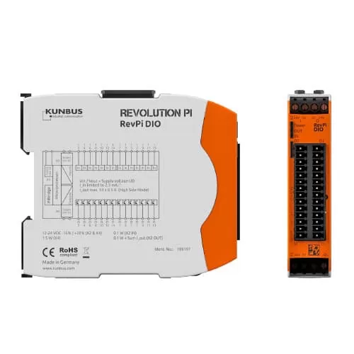
Description
| Housing dimensions (H x W x D) | 96 x 22.5 x 110.5 mm |
| Housing type | DIN rail housing (for DIN rail version EN 50022) |
| Housing material | Polycarbonate |
| Weight | approx. 100 g / 130 g (incl. connectors) |
| IP Code | IP20 |
| Power supply | 12-24 V DC -15% / +20% (X2 and X4) 1 |
| Max. power consumption | 1.5 Watt (X4/power supply) |
| Operating temperature | -40 °C….+55 °C |
| Storage temperature | -40 °C….+85 °C |
| Humidity (at 40°C) | 93% (non-condensing) |
| Connectors | 2 x 4-pole screw-type terminal for power supply 2 x 14-pin socket connectors with spring clamp contacts (0.2 – 1.5 mm²) for IOs, pitch 3.5 mm (Wieland Item No. 27.630.4453.0) |
| Optical indicator | 3 status LEDs (bi-color) |
| Number of digital input channels | 14 |
| Input type | Galvanically isolated from the system bus and from the outputs, individually configurable as direct digital input, counter rising edge, counter falling edge or together with neighboured input as encoder 2 |
| Input current limitation | 2.4 mA (at 24 V power supply) |
| Input thresholds | At 24 V compatible according to EN61131-2 to Type I and III sensors |
| Digital debounce circuit | Collectively adjustable for all inputs: off, 25 µs, 750 µs or 3 ms |
| Maximum frequency resolution of the counter inputs | 2 kHz (corresponding to 500 Hz encoder sequence) |
| Alarm | For auxiliary voltages below 19 V and below 9 V, overtemperature |
| Input protection | According to EN 61131-2 (IEC 61000-4-4, -5, -6, and -2) against overvoltage, negative voltages, burst, surge, ESD, RFI |
| Number of digital output channels | 14 |
| Output type | Galvanically isolated from the system bus and the inputs, individually configurable as direct digital output with high-side or push-pull drivers as well as a PWM output 3 |
| Maximum current per output | 500 mA (high-side mode), 100 mA (push-pull mode) |
| PWM frequency | Collectively selectable for all outputs: 40 Hz, 80 Hz, 160 Hz, 200 Hz, 400 Hz 3 |
| Alarm | Thermal shutdown or short circuit of outputs (individually for each output) |
| Dual watchdog function | In the event of communication failure with the controller (after 50 ms) or internal communication with the CPU (after 9 ms, hardwarecontrolled), the outputs are reseted to zero |
| Output protection | According to EN 61131-2 (IEC 61000-4-4, -5, -6, and -2) against short circuit, overload, external voltage, negative voltages, burst, surge, ESD, RFI |
| Compatible modules for system expansion | All RevPi base module, expansion modules and RevPi Gate modules (connected via overhead PiBridge connector) |
| Protection of the power supply inputs | Reverse polarity protected, overvoltage protection |
| CE conformity | Yes |
| RoHS conformity | Yes |
| Surge/Burst tests | Passed (according to EN61131-2 and IEC 61000-6-2) |
